ectret WB4IUY's Modifications & Fixes Page
   
Dave Hockaday WB4IUY, Youngsville NC USA FM05

Modifications, Fixes, & Patches

AM Filter for the Icom 756 (non-Pro model)

I've been looking for an AM filter for my IC-756 for many years, and just stumbled across a filter from W2ENY. I think he used to offer these, and went out of production for some number of years. He has brought a limited number of these back for sale. I emailed him, he replied almost immediately that he still had some, and I ordered one. I'm happy to have finally found one of these babies. I work AM from time to time on 160 thru 10, and usually operate one of my boatanchors due to the w-i-d-e passband on AM. His page is:

https://www.w2eny.com/6kc_filter/

I received the 6khz AM filter from W2ENY for my IC-756. The instructions were EASY to follow and the mod was quick and simple. I LOVE it! I've been working AM on 80, 40, and 15m with the 756 and have great selectivity on AM. I replaced the 15khz filter in the 455khz I.F., and have noticed no issues with working FM on 10m, listening to broadcast stations, etc. My 18 year old IC-756 is now perfect in my opinion, and everything is working great. This is the filter the rig should have come with from the factory, as all modes are well behaved, now.

UPDATE: 3/16/14... After using the filter for about a year, I felt the need to make another change. The instructions from W2ENY mentioned to replace the 15khz filter in the 455khz I.F. with the 6khz AM filter. I found, when operating AM on 10m, it is desirable to have access to the 15khz filter to open up the receiver a bit for the broadcast audio often heard on AM. Also, when working 10m FM, the 9khz filter in FM narrow is a bit too narrow for good audio and clipping would occur. I never found a need for the 9khz filter in AM or FM operation, but I constantly found the need for the 15khz filter. So, I reinstalled the 15mhz filter and installed the AM filter (6khz) in the place of the 9khz filter, and all is now well. Just my $01 worth, but it sure works out better at my QTH in this configuration.

756 455 khz Filter Location


756 AM Filter

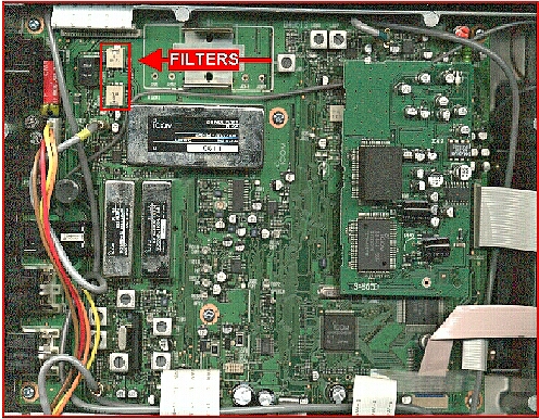
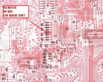
60m Modification for the IC-756 Standard (non-Pro)

Modifying the ICOM IC-756 Standard (non-Pro model) for 60m takes a little work, but it's worth the effort. First, the transmitter has to be opened up for general coverage operation. That's pretty easy. Here's the info for the first phase of the modification...

Remove bottom cover. On the MAIN board you will see IF filters and a daughter board (DSP filter) on the right side. The W805 jumper and IC803 chip is located under the DSP board. You have to remove the DSP board (carefully) and look for the part labeled IC803 and the line of SMD jumpers (little green parts). Locate and unsolder the W805 jumper. Re-Install the DSP board and put the bottom cover back. A pic of the jumper location on board is n the right, as is a a pic of the jumper on my fingertip after removal.

When I first modified the processor, as I had seen numerous bits around the web for adding 60m, it worked 'OK', but would only put out about 50% power on 60m. I found that the band matrix is setup to use the 80m low pass filter up to 6.0 mhz, where it transitions to the 40m filter. W6FM had the IC-756 Pro II and modified his for 60m coverage as I did, and had the same problem with low output power. He had access to some filter design software, and modeled the 80m filter to see where the problem was. He came up with a few capacitor changes to alter the knee of the filter response to fix the problem in the Pro II. I checked the manuals and board layouts against each other, and while the filter units in the standard and Pro II are physically a little different, the circuit was the same. I ripped mine apart tonight and dove in. Change C7, C66, & C69 to 180pF disc. Change C15 to a 270pF disc. This moves the knee of the filter from 5.25mhz to 5.6 mhz. The end result was awesome...full power right up to the edge of the 60m band and no purity issues. One of the pics here is the filter as modeled in software, the violet curve is before mods, the white curve is after mods. The other pic is of the filter unit.

One last note...the internal antenna tuner isn't mapped to work correctly on the 60m band, but the rig works great with an external antenna tuner or with a resonant antenna. Hope this helps some of you with your 756 to enjoy 60 meters. The filter mods will also work with the Pro II once you use the appropriate mod for general coverage transmit. Many thanks to W6FM for the filter model work!

756 TX FIlter Board


60m Band on screen


Location of Caps n board


Filter as modelled


SMD Jumper

ICOM 756 ALC Mod for AM

This is a simple circuit that is used to trick the 756's ALC circuit into allowing the transmitter to operate with upward modulation when operating AM. I ran several tests and always got best transmitted signal quality reports when operating with it in place. There is a simple schematic and description on this site, and can see it by clicking HERE.

ALC Power Supply

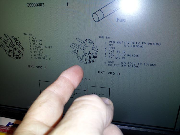
Yaesu FV-101DM mod for use on FT-901 series radios

I have a FV-101DM and a FT-901DE (same remote VFO requirements as the FT-901DM and the FT-902 series). I've seen several notes from people who thought they would directly interface, and decided to dig into this and get mine working. After reading the notes around the web, I studied the schematics and realized that they are incorrect and would have 12vdc being applied to the VFO output and the wrong cable being modified for operation.

The FT-901Ds have a totally different interconnection design from that of the 101ZD's. The 101ZD's have two cables between the VFO and transceiver, the 901Ds utilize one. Additionally, the FV-101Z & FV-901DM have a different pinout on VFO port B than the FV-101DM.

After a bit of experimentation, I discovered the FV-101DM can be interfaced to the FT-901DM with a little work, and retain most of the functionality of the FV-101DM's original design. Here's what has to be done:

1- A jumper must be installed from pin 7 of port A to pin 1 of port B on the VFO.

2- The 6-pin cable supplied with the FV-101DM only utilizes 3 wires (with no shielded circuits for the VFO output), as it intends for the VFO communications to the 101ZD to be via VFO port A. For this reason, a new cable with 6-pin connectors must be assembled to connect from the FT-901DM to the FV-101DM VFO port B. Wire the cable, pin to pin (i.e. Pin 1 to pin 1, pin 2 t pin 2, etc). Use a piece of small coaxial cable with the center conductor connecting pin 1 to pin 1, and the shield connecting pin 2 to pin 2. Standard unshielded wire is fine for the other pins.

3- Assemble a power cord to plug into port A on the VFO, to supply an external 12 vdc source to pin 1. Include a fuse link at 250ma to protect the circuit in the event of a problem. Connect the negative of the 12 vdc source to the cabinet of the VFO (there is no ground connection in the socket for port A on the VFO).

That's it! Mine is working great, and has all functionality except the VFO memories can not be programmed from the FT-901DM, but can be programmed from the VFO just fine. This is because there is no feedback path from the FT-901's internal VFO to the FV-101DM VFO like there is with the FT-101ZD.

Buxcomm Rascal Interface


Buxcomm Rascal Interface


Buxcomm Rascal Interface


Buxcomm Rascal Interface

Buxcomm Rascal Interface Mod for CW

I've made a mod to the Rascal for keyed CW, so I wouldn't have to change cables when I operated in CW (not MCW) mode. I've posted info and a drawing about this on the site, and you can see it by clicking HERE.

Buxcomm Rascal Interface

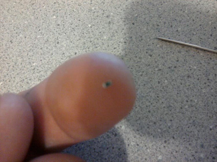
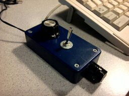
SSB Squelch Mod for my Icom IC-211

I've got an old Icom IC-211 for 2m ssb. It's one of the early units from the late 70's where the squelch isn't designed for SSB use, and only functions in FM mode. I looked into the circuit, and it didn't seem practical to mod it for use on SSB. I've toyed around with the idea of adding a squelch circuit to the rig using an old squelch board from a Motorola Micor, as I have lots of them in junk and I was able to crowbar it into service on the workbench, but it was designed to work with discriminator audio and was kinda quirky. 
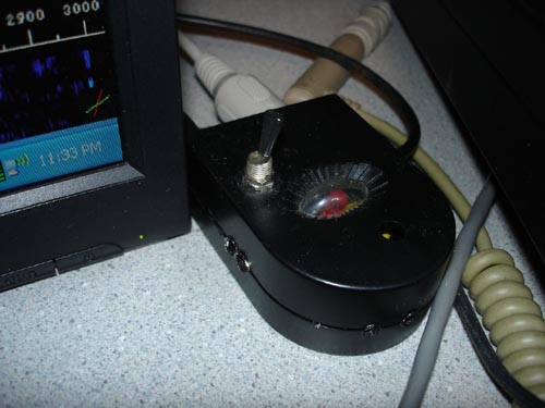
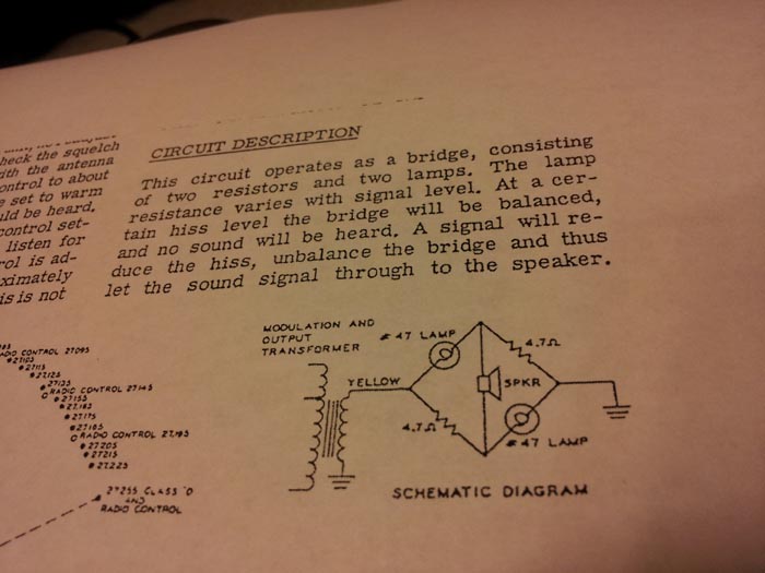
I decided to borrow an old idea from a Heathkit mod for the old 2'er Lunchbox from back in the 60's... This is a simple 
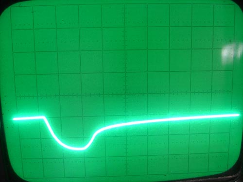
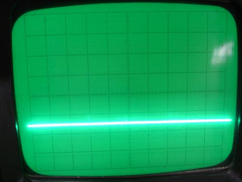
bridge circuit using 2 incandescent lamps and two resistors. It works great... Check out the two pics and the video. Gonna mount it inside the speaker with a switch to bypass it.

In this case, the audio current of constant static brings the lamps to a stable resistance value to balance the bridge. When voices are present, the current varies and causes the lamps to change resistance, which unbalances the bridge. Audio passes to the speaker when unbalanced. It's not a perfect squelch, but for an old radio on a band that has a constant static level (more or less), it's working great. Cheap, too! I love building things from junk :-)

I've experimented with this, and found it to work with pairs of other similar lamps like the #44, #267, #755, #1847, #1866, #159, #259, & # 447. You mainly need lamps with a filamant voltage of about 6 volts and current of about 150 to 250 ma. Click this link to see a little video I took with my phone of the operation of the Old School Squelch.

Squelch Schematic


Assembled Squelch

AM mod for the Heathkit SB-401 Transmitter

The mods are fairly simple, and I'm working on marking up my schematic for scan and upload here. I made these mods back around '96 or so. Here's what I did:

- Install a 4pdt switch to control the "AM Override Mode" while in CW

- Use one pole of the switch to activate a small relay to bypass the TX crystal filter with a .01 uF cap (to pass both sidebands). I could have wired this directly to the switch, but used a small relay to keep the leads to and from the filter as short as possible.

- Use one pole of the switch to open the CW Sidetone circuit during transmit

- Use one pole of the switch to reconnect the PTT circuit in CW mode

- Use one pole of the switch to disable to the CW delay when in "AM Override" mode.

I set the transmitter to CW mode, set the new "AM Override" switch to "ON", adjust the mic gain/CW level front panel control to set plate current at about 75-100ma. This provides about 10-15 watts out. I feed this into my old Gonset GSB-201 MKIII amp for about 175 watts of carrier, and it plays well. I did build an electret condenser mic element into an old Turner Desk Microphone housing, and bias it with a 9v battery... this really improved my low frequency response. This setup sounds great and has an audio response from about 85hz to over 5khz.

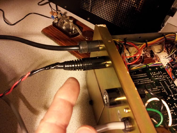
Transmitted Hum Fix for my FT-901 Yaesu

I had never tried to operate my old FT-901 on AM until recently, and discovered a 60 hz hum on the output signal. I could see something on my Heathkit TX scope and couldn't tell what the freq was, but one of the guys on 3707 identified it as 60hz with his audio scope.

My first thought was a problem of some sort in the audio chain...ground loop, bad ground on the mic, etc... I listened to the mic audio chain through the monitor function on the rig and it sounded clean as a whistle, but I didn't know where that was sampled. I shorted the mic input and tx'd manually...still had the hum. I poked around in the audio chain with the signal tracer and couldn't find any hum. I finally cut the audio chain completely loose, and still had hum. I could hear it in CW, though very subdued. When in AM, it's wasn't very strong with the carrier cranked up for some reason, but down at the 75ma plate current level I needed to operate at for AM, it seemed to really modulate the tx.

The driver and finals were soft, so I replaced and neutralized them, just in case it was something in the tubes, but it wasn't.

I looked in the power supply to see what was 1/2 wave rectified (since it was 60hz). I looked in the rect A, B, & C boards and found the -120vdc bias supply had about 30v of 60hz ripple. I recapped the board, no improvement. I experimented a little and found I could connect a 33uf @ 450 vdc cap from pin 6 of rect A bd (-120vdc bias supply) to ground, and would completely clean up.

Here's a couple of pics from my HP scope, of the bias supply. The resolution is set to display one sine at 60hz, at 20vdc per division. The first one shows a ripple of 30 volts! The second pic is after the addition of the 33mF cap to the bias supply.

FT-901 Bias Supply Before


FT-901 Bias Supply After

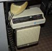
Motorola Micor Mods for 70cm Amateur Use

This project started back in 1991, when several of us bought a load of Motorola Micors for about $15 each from the NC State Surplus. They were pulled from the NC Forestry Service vahicles, and were in abundant supply. They are a very durable radio, have a sensitive receiver, and many of them had 100w PAs. Since almost none of us had 440 mhz radios, we turned this into a club project to get a lot of folks on 70cm at one time. There was a local repeater on 444.000 mhz, so we ordered a batch of crystals and got started. We shortened up the remote head cables, eliminated all of the unwanted cables, and wrote an alignment process. Click the pic to the right of my old Motorola Micor (still in use!) to get the mod in microsoft word format.

Motorola Micor UHF

Motorola Micor Mods for a 70cm Amateur Repeater

We had so many of these Motorola Micors, we decided to build another repeater from them as well. We could have easily stacked two of the rigs for rx & tx, but we wanted to try and make one radio operate full duplex. It will do it, and we still have one of them running on 442.400- and it has been on the air continuously since 1993! Click the pic to the right to get the repeat mods in microsoft word format. You can also see our Micor 440 repeater in operation at the following links: LINK 1 and LINK 2.

Motorola Micor UHF Repeater

Motorola Micor Mods for 220mhz Amateur Use

Wow...we had SO many of these radios from the previous projects, that we decided to try the mods we found online for 220 mhz operation. They work well, and is documented in the following mods. Click the pic to the right of my old Motorola Micor (still in use!) to get the mod in microsoft word format.

Motorola Micor 220mhz


free counters